Comparing Stepper Controller Boards
The available selection of stepper motor controller boards is pretty good these days. The arena has matured to the point where top-of-the line boards from years back are now mass-manufactured and sold for extremely low prices. There’s also an interesting selection of next-gen controller boards using 32-bit 100Mhz+ microcontrollers - most of which have been surprisingly slow to gain market share over the old 8 bit 16Mhz variety.
The RepRap Wiki electronics page provides a pretty good overview of the available controller boards. The tried and true RAMPS board is by far the most popular by quantity, and one of the best supported by various firmware. The board is relatively underpowered by today’s standards, but makes up for it in community support. On the other end of the spectrum is the RasPi or BeagleBone based boards running a full Linux OS with stepper controller code in higher level languages like Python. The hardware is very capable, but cost limits adoption, and low adoption limits motivation to write and maintain firmware/software. In the middle of the road are boards developed with more modern 32 bit microcontrollers running in the 100Mhz range - these will eventually take off as the RAMPS replacement and enable new features for 3d printers and CNC machines.
| Board | Hardware | Firmware | Cost |
|---|---|---|---|
| RAMPS | 16Mhz ATMega2560 | Sprinter, Teacup, Marlin, Repetier, grbl, etc… | $30-$60 |
| Rambo | 16Mhz ATMega2560 | Teacup, Marlin, Repetier, etc. | $120 |
| TinyG | 32Mhz ATxmega192 | Grbl based custom firmware | $130 |
| AzteegX5 | 120Mhz LPC1769 | Smoothieware | $113 |
| SmoothieBoard | 120Mhz LPC1769 | Smoothieware | $100-$150 |
| Duet | 120Mhz Atmel SAM4E8E | DuetFirmware | $160 |
The Azteeg, SmoothieBoard and Duet are pretty nice, but perhaps it’s hard to justify the cost when a $40 RAMPS setup (Arduino + RAMPS shield + stepper drivers + LCD) (amazon link) appears to perform the same task. Even the new Prusa i3 MK3 is still using an 8-bit ATMega controller (the EINSY RAMBo).
So why use a more modern stepper motor controller?
A few things enabled by more processing power:
- Connectivity (ethernet, wifi, bluetooth, etc)
- Higher Microstepping (from 16/32 to 256; also depends heavily on the stepper driver chip)
- Increased Step Rate (from ~10Khz to ~500Khz)
- Improved Path Planning (longer lookahead, smoother acceleration profiles)
- More overhead for monitoring
Step rate, step accuracy, and path planning are particularly interesting because they’re difficult to measure. It’s also interesting that some of the new 32 bit 100Mhz controllers are running code ported from the 16Mhz 8 bit world, where shortcuts (at the expense of clean steps) were taken out of necessity. How long will these inaccuracies persist even into the 32 bit controller era?
One thing is for certain, if nobody identifies a problem, nobody will fix it!
Analyzing Step Accuracy
A high step rate is only useful if the steps are also accurate. Are the steps correctly spaced? Are steps from multiple axis aligned properly? And how can we even analyze details this small? Enter the Logic Analyzer! I’ve got a USB logic analyzer from Saleae which has a measurement accuracy of +-42nS, and can capture a huge number of logic transitions. When capturing step/direction waveforms, it’s about 1-2MB per second when all axis are moving at their fastest speed - meaning I can capture many minutes of steps before I run out of space.
For the first test, I loaded up grbl v1.1 on my old Arduino Uno and ran the following GCode:
G1 X10 F6000
G1 Y10 F6000
G1 Z10 F6000
G1 Z-10 F6000
G1 Y-10 F6000
G1 X-10 F6000
G1 X0 Y0 Z0 F6000
G1 X10 Y20 Z-40 F6000
G1 X40 Y-40 F6000
G1 X10 Y0 F6000
G1 X0 Z0 F6000
G1 Z-100 F6000
G1 Z100 F6000
G1 Z0 F6000
G1 X1 Y1 Z1 F6000
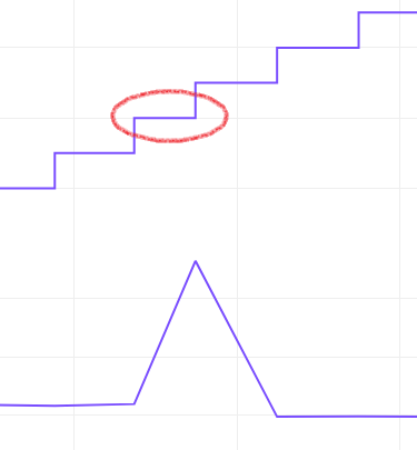
G1 X0 Y0 Z0 F6000Configured to run at 100mm/s, accelerate at 100mm/s^2, and a step rate of 100 steps/mm, the GCode produces this position, velocity, and acceleration profile. The maximum step rate in this motion is 10K steps/second.
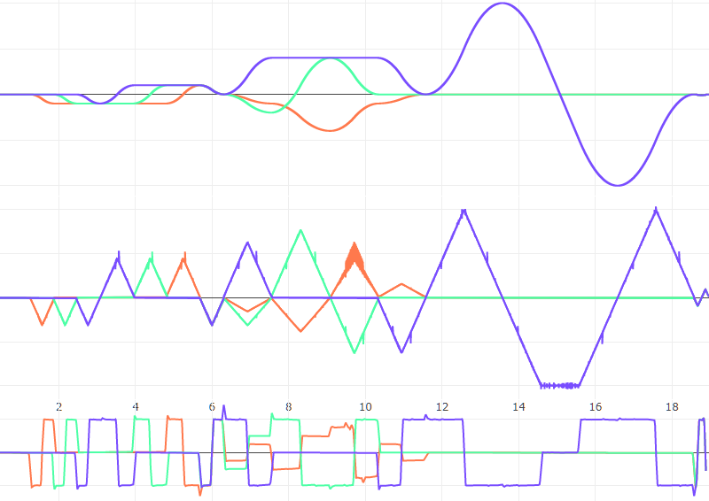
The position paths are generated by simply following the step and direction signals. The velocity paths are created by taking the difference between two points in the position path. The acceleration path is a bit more interesting - if acceleration is computed from velocity deltas (how velocity is computed from position), the result is an incredibly noisy graph. This is because every derivative amplifies any error from the source data. So the data is cleaned up by sampling at a high rate and passing through a low pass filter. The result is reasonable, but with the caveat that spikes might not represent actual acceleration changes (especially if they’re near a position of zero velocity where steps are infrequent).
The acceleration graph is useful for getting a general idea of the motion profile. In this case, the grbl firmware is generating a constant acceleration motion profile - which is adequate for most 3d printers and anything with a high rigidity-to-inertia ratio. There are better profiles, but more on those in a future post…
What’s more interesting here are the spikes in velocity. Those aren’t an artifact, they’re an actual slow or fast pulse:
And there’s one section of the graph that has a LOT of velocity spikes:
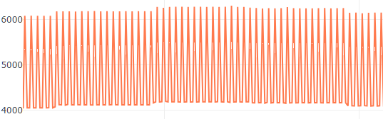
The magnitude of the spike is about 2000 steps/second, more than a third of the desired velocity. This is probably some form of Bresenham’s line aliasing problem; the lead axis is set to travel to 40mm, and the follower axis (this one) travels to 30mm. The frequency is about 1.7Khz, which is likely too high to excite any mechanical resonances - but could have some audible effects. There may be effects on the torque, power, and heating too since the current will oscillate against the inertia of the motor and connected mechanical components.
Exactly what effects these spikes have will be the topic of a future post, as will investigations of other stepper controller boards. If you’ve got any questions or ideas for boards/other things to check out, send me a message on Github!